
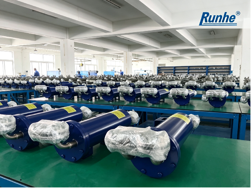
API Plan 21: Process fluid is taken from the pump discharge, cooled via the heat exchanger and then returned to the seal chamber.
Circulation is driven by the pressure differential between the pump suction and discharge.
API Plan 23: Independent closed‑loop circuit. Fluid inside the seal chamber circulates through the heat exchanger for cooling, driven by the integral pumping ring of the mechanical seal.
1. Heat Load
Heat generated at the mechanical seal faces is the primary parameter. Plan 21 cools high‑temperature process fluid taken directly from pump discharge and generally carries a higher heat load. Plan 23 only
removes heat generated by seal faces plus heat conducted from the pump casing to the seal chamber, resulting in a relatively lower heat load. A higher heat load requires a larger required heat transfer area and a
correspondingly larger heat exchanger. A safety margin is normally reserved during selection to avoid seal failure caused by overheating.
2. Log Mean Temperature Difference (LMTD)
This refers to the temperature difference between the process fluid and cooling water. A larger temperature difference improves heat transfer efficiency, allowing a smaller heat exchanger to be selected. A smaller
temperature difference requires a larger heat transfer area and a bigger cooler shell.
3. Overall Heat Transfer Coefficient
It is affected by fluid viscosity, thermal conductivity and fouling tendency. For working media with high viscosity or high fouling potential, heat transfer performance declines.
A larger heat transfer area shall be reserved during equipment selection, which means a larger‑size heat exchanger.
4. Circulation Flow Rate
Fluid circulation for Plan 21 is driven by the pump suction‑discharge pressure differential. For Plan 23, closed‑loop circulation is driven by the integral pumping ring fitted within the mechanical seal.
Circulation flow rate directly determines cooling capacity. A small heat exchanger cannot dissipate heat sufficiently if the flow rate is insufficient.
5. Allowable Pressure Drop
This represents pressure loss across piping and the heat exchanger. Circulation in Plan 21 is powered by pump pressure difference and tolerates higher pressure drop. The pumping ring in Plan 23 provides limited
driving head. Excessive pressure drop will reduce circulation flow rate. The dimensions and internal tube bundle structure of the heat exchanger must take pressure drop into account during selection.
6. Maximum Operating Temperature
The core purpose of heat exchanger sizing is to keep the seal chamber temperature within a safe operating range. Higher incoming process fluid temperatures require heat exchangers with greater cooling
capacity to maintain stable sealing performance.
#Heatexchangersizing#APIPlan21#APIPlan23# Pumpmechanicalseal#Tubebundleheatexchanger#Heatload


 export@rhseal.com


